Stair Climbing Robot
Our Goal
We wanted to build a robot capable of climbing full size stairs and driving at a reasonable pace. This robot should also be able to carry the load of an average adult to act as a way to ascend stairs for those reliant on wheel chairs.
We won't be the first to create this kind of robot, but ours will be one of the rare builds capable of climbing full sized stairs. Below are two videos that inspired this project. One is a powered robot like ours, capable of climbing stairs, the other is a passive trolley, not powered but able to climb full sized stairs.
We won't be the first to create this kind of robot, but ours will be one of the rare builds capable of climbing full sized stairs. Below are two videos that inspired this project. One is a powered robot like ours, capable of climbing stairs, the other is a passive trolley, not powered but able to climb full sized stairs.
Design
We designed and built the mechanical systems in the machine from the ground up. Though many similar projects like this have been done in the past, we were forced to rethink and simplify our design. Where most robots using a mechanism like this use a differential to drive the wheels and tri-star as desired from the same motor we used a new method: planetary gears.
Most tri-star stair climbers use the differential to drive both the wheels and the tri-star with a single motor. The motor drives the differential case and each system is driven from one of the two outputs. With the stair climbing system, the power from the motor isn't forced to be distributed evenly like in an automobile, rather, it is free to travel along whichever path offers the least resistance.
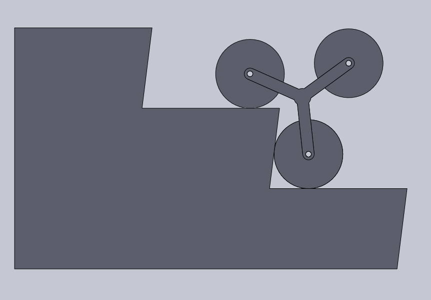
On a flat surface, the wheels are easier to turn than the tri-star because the wheels are round and roll easily but the triangle lifts the entire robot and is opposed by gravity. As a result, when on flat ground, only the wheels turn. However, once the wheels hit some kind of obstacle like a wall or stairs, the front wheel of the robot gets stuck. This causes the wheel system to become more resistive than the tri-star system. When this happens, the power gets diverted from the wheels to the tri-star and causes it to climb.
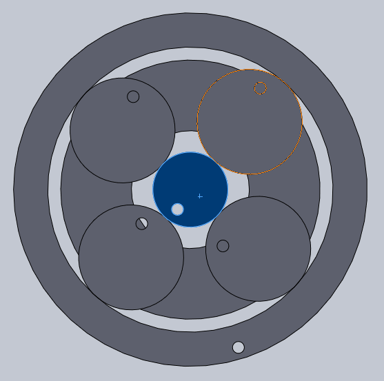
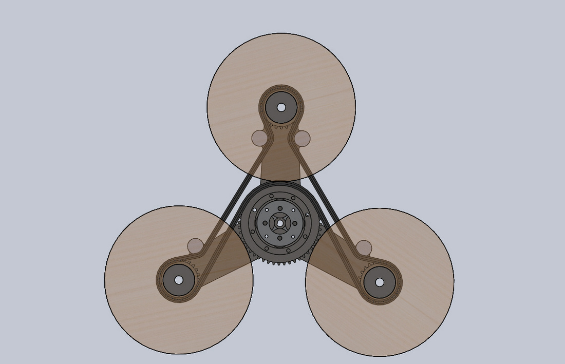
So how did we get this to act the same way a differential does? Usually a planetary system is used by holding one of the three components. Often the sun (shown in yellow) at the center drives, the planet carrier (shown in green) acts as an output, and the ring, or annulus (shown in pink), is held in a case which bolts to the motor to hold the system steady. In our design, we used the sun as an input as expected, but instead of holding either the ring or the planet carrier, we made both components outputs. The annulus drives the wheels and the planet carrier drives the tri-star.
If the tri-star is more difficult to turn, as is expected on flat ground, the planet carrier is held still and the power moves from the sun, through the planet gears (shown in blue) to the annulus to drive the wheels. If the wheels are blocked against stairs, a wall, or some other significant obstacle, the annulus is held still and the planet carrier is driven to rotate the tri-star.
Most tri-star stair climbers use the differential to drive both the wheels and the tri-star with a single motor. The motor drives the differential case and each system is driven from one of the two outputs. With the stair climbing system, the power from the motor isn't forced to be distributed evenly like in an automobile, rather, it is free to travel along whichever path offers the least resistance.
On a flat surface, the wheels are easier to turn than the tri-star because the wheels are round and roll easily but the triangle lifts the entire robot and is opposed by gravity. As a result, when on flat ground, only the wheels turn. However, once the wheels hit some kind of obstacle like a wall or stairs, the front wheel of the robot gets stuck. This causes the wheel system to become more resistive than the tri-star system. When this happens, the power gets diverted from the wheels to the tri-star and causes it to climb.
So how did we get this to act the same way a differential does? Usually a planetary system is used by holding one of the three components. Often the sun (shown in yellow) at the center drives, the planet carrier (shown in green) acts as an output, and the ring, or annulus (shown in pink), is held in a case which bolts to the motor to hold the system steady. In our design, we used the sun as an input as expected, but instead of holding either the ring or the planet carrier, we made both components outputs. The annulus drives the wheels and the planet carrier drives the tri-star.
If the tri-star is more difficult to turn, as is expected on flat ground, the planet carrier is held still and the power moves from the sun, through the planet gears (shown in blue) to the annulus to drive the wheels. If the wheels are blocked against stairs, a wall, or some other significant obstacle, the annulus is held still and the planet carrier is driven to rotate the tri-star.
Manufacturing
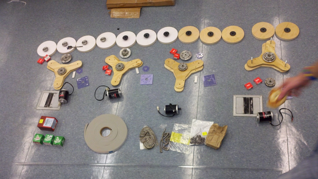
Manufacturing can be broken down into 3 major assemblies: the drivetrain, tri-wheel, and chassis. The build of each component offered it's own challenges to overcome.
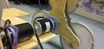
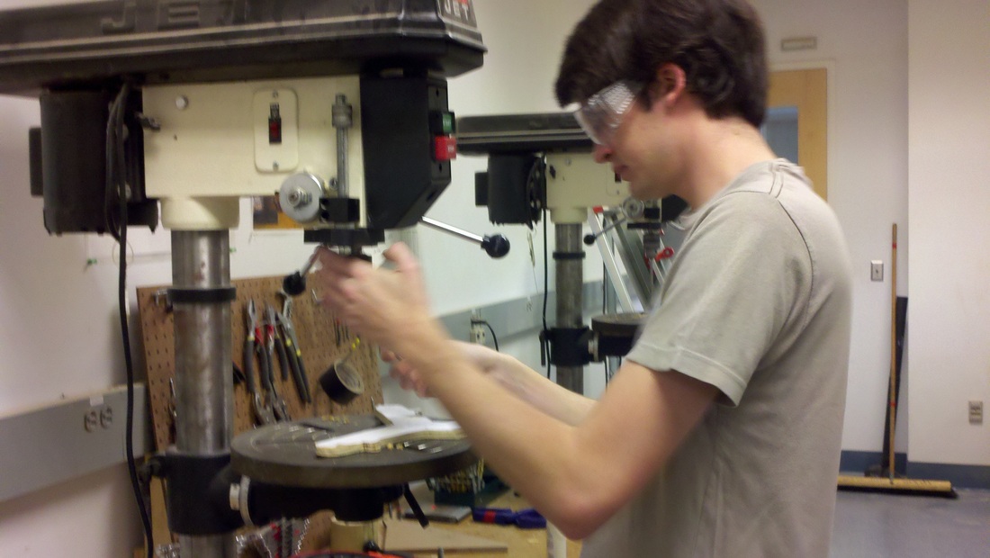
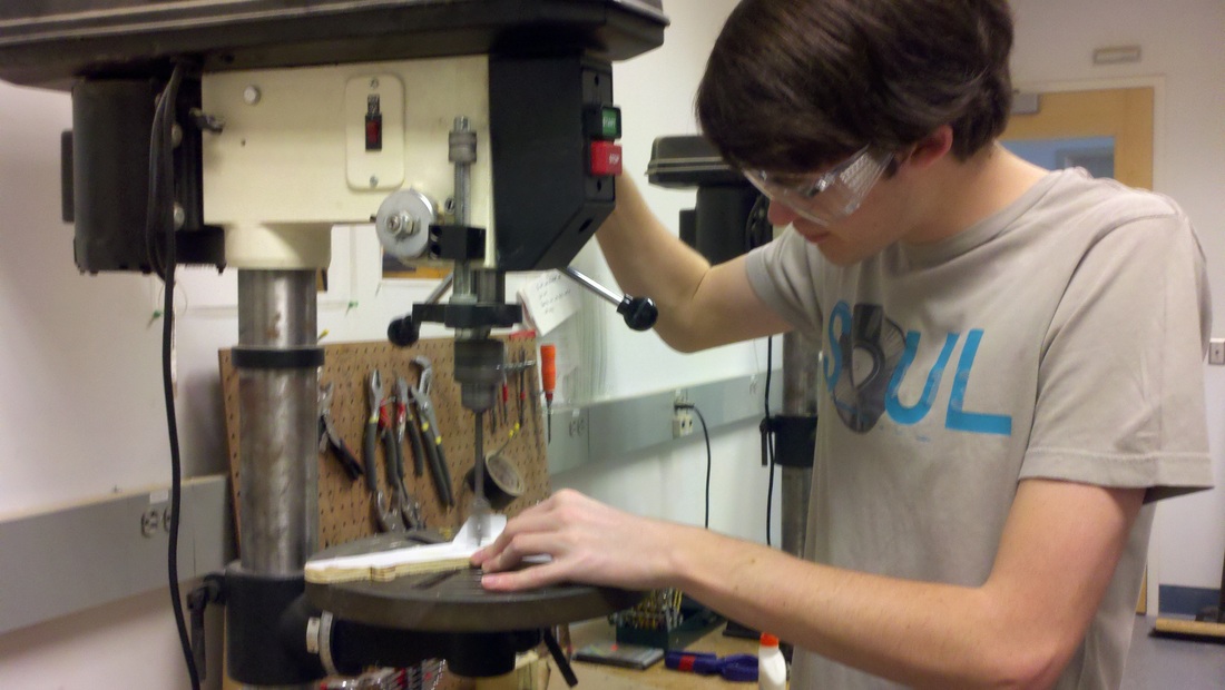
The drivetrain includes the planetary gears, sprockets, and chain. These components required extensive milling and metal work. The first issue we addressed was modifying sprockets that we had found so that they would fit in our design. The central sprocket needed a large hub removed so that it could be bolted to the planetary gear. This was CNC-milled for time and efficiency, plus the benefit of more-accurate drilling of bolt holes.
Due to using two planetary gears to connect the motor to the tri-wheel, it was necessary to manufacture our own driveshafts. We used 8 mm steel, cut to 3 inch lengths with a portion of the top removed to create a D-shape, thus allowing it to interface with the inner spline of the outer planetary gear. To mount this to the inner planetary, a plate was made our of ¼” thick, 1” wide aluminum stock.
Lighter manufacturing included remove some material from some of the smaller hubs so that they were all the same thickness. This would allow us to use our custom-made delrin spacers interchangeably. We originally planned on making delrin chain tensioners, but did not have the budget to create bearing-mounted tensioners. Rather than using a shaft that the chain would run against (chain would wear through this very quickly), we used acrylic plate. Whilst creating somewhat more drag, it would be more resistant to the chain. This was an acceptable trade-off.
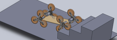
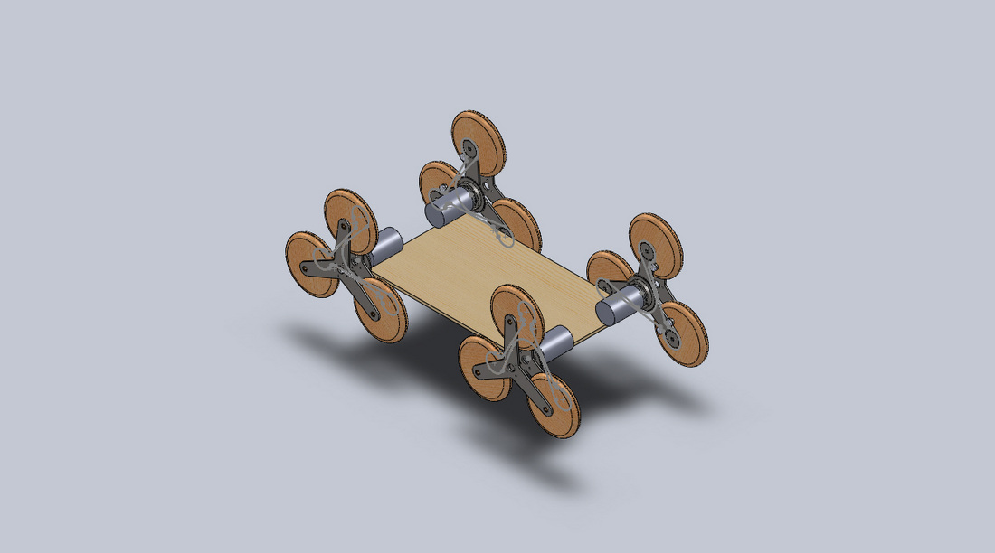
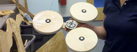
Originally we only planned on using wood to make prototypes of the y-frame and wheels. However, as our budget became more finalized, it was apparent that we would not have the ability to make these components out of plastic composite or metal. We modified our designs accordingly and made 8 y-frames and 12 wheels out of scrap wood. Wood had the advantage of cheapness, availability, and weight. Whilst the entire robots weighs roughly 30lbs, most of this is due to the steel components found in the drivetrain.
The all of the drivetrain components sandwich between 2 y-frames with large diameter steel bolts holding the entire thing together. Each y-frame contains a bearing to reduce mechanical friction and increase efficiency.
The chassis is a simple wooden sheet with sections removed for the tri-wheels to rotate. The motors are mounted using acrylic plates drilled into the side. When sitting, each wheel assembly wants to torque inwards, pressing the motors into the plate. Originally we thought that they would require additional attachment, but to date that has not appeared necessary.
To stabilize the wheel assemblies and add a second point of support, we created a side rail that extends along the length of the edge of the robot. It is attached to the chassis with two screws into the chassis plate and two custom aluminum corner braces. The ends of the of the rail seat 8 mm bolts that fit into the y-frame bearing.
The drivetrain includes the planetary gears, sprockets, and chain. These components required extensive milling and metal work. The first issue we addressed was modifying sprockets that we had found so that they would fit in our design. The central sprocket needed a large hub removed so that it could be bolted to the planetary gear. This was CNC-milled for time and efficiency, plus the benefit of more-accurate drilling of bolt holes.
Due to using two planetary gears to connect the motor to the tri-wheel, it was necessary to manufacture our own driveshafts. We used 8 mm steel, cut to 3 inch lengths with a portion of the top removed to create a D-shape, thus allowing it to interface with the inner spline of the outer planetary gear. To mount this to the inner planetary, a plate was made our of ¼” thick, 1” wide aluminum stock.
Lighter manufacturing included remove some material from some of the smaller hubs so that they were all the same thickness. This would allow us to use our custom-made delrin spacers interchangeably. We originally planned on making delrin chain tensioners, but did not have the budget to create bearing-mounted tensioners. Rather than using a shaft that the chain would run against (chain would wear through this very quickly), we used acrylic plate. Whilst creating somewhat more drag, it would be more resistant to the chain. This was an acceptable trade-off.
Originally we only planned on using wood to make prototypes of the y-frame and wheels. However, as our budget became more finalized, it was apparent that we would not have the ability to make these components out of plastic composite or metal. We modified our designs accordingly and made 8 y-frames and 12 wheels out of scrap wood. Wood had the advantage of cheapness, availability, and weight. Whilst the entire robots weighs roughly 30lbs, most of this is due to the steel components found in the drivetrain.
The all of the drivetrain components sandwich between 2 y-frames with large diameter steel bolts holding the entire thing together. Each y-frame contains a bearing to reduce mechanical friction and increase efficiency.
The chassis is a simple wooden sheet with sections removed for the tri-wheels to rotate. The motors are mounted using acrylic plates drilled into the side. When sitting, each wheel assembly wants to torque inwards, pressing the motors into the plate. Originally we thought that they would require additional attachment, but to date that has not appeared necessary.
To stabilize the wheel assemblies and add a second point of support, we created a side rail that extends along the length of the edge of the robot. It is attached to the chassis with two screws into the chassis plate and two custom aluminum corner braces. The ends of the of the rail seat 8 mm bolts that fit into the y-frame bearing.
Electrical System
The electrical system of our robot is both simple and robust. It can be separated into three segments: the power source, the control, and the signal transition/ reception.
Through the course of project, we tested a variety of power sources. We began with a single 12V 17.2 Ah Sealed Lead Acid battery; this was the cheapest and more readily available option we had. However, our experimental testing concluded that this power source would be too weak and possibly too heavy. With the knowledge that our motors were designed to handle up to 24V, we added a second SLA battery in series with our original battery. This provided the motors their maximum 24V, but doubled the weight of the power source. Initially, we saw a drastic increase in performance, but it quickly became clear that the robot would not be able to climb while carrying the two large batteries. For this reason, we decided to use a 22.2V 5000mAh Li-Po battery as our final power source. While this battery can only provide roughly one-third the operational time as the SLA batteries, the Li-Po battery is approximately one-ninth the weight of the SLA and is light enough to be carried by the robot up an incline.
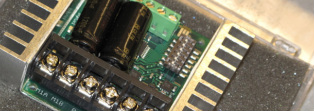
The control component of the robot is the most complicated aspect of the electrical system. At its heart, the robot is controlled by two Sabertooth 2X25 Speed Controllers. Each speed controller drives two motors at maximum continuous rate of 25A with a peak current output of 50A per motor. The motors are driven with a pulse width modulation, or PWM. This allows the motors to provide their full torque, even at low speeds. The speed controllers are also programed to have exponential control, instead of a standard linear control. This allows for smoother manipulation of the robot, giving precise control on the low end and quicker control on the high end.
Both speed controllers are connected to a 2.4 gHz Spectrum receiver, which is then wireless connected to a 2.4 gHz Spectrum transmitter. The operator manipulates the thumb-sticks on the transmitter and the corresponding signals are sent to the receiver on the robot. Steering is accomplished in a tank-steering manner; when the operator sends the signal to turn right, the left set of wheels spin faster than the right set, driving the robot in an arc to the right. The same method is use to turn to the left. This completes the electrical system.
Through the course of project, we tested a variety of power sources. We began with a single 12V 17.2 Ah Sealed Lead Acid battery; this was the cheapest and more readily available option we had. However, our experimental testing concluded that this power source would be too weak and possibly too heavy. With the knowledge that our motors were designed to handle up to 24V, we added a second SLA battery in series with our original battery. This provided the motors their maximum 24V, but doubled the weight of the power source. Initially, we saw a drastic increase in performance, but it quickly became clear that the robot would not be able to climb while carrying the two large batteries. For this reason, we decided to use a 22.2V 5000mAh Li-Po battery as our final power source. While this battery can only provide roughly one-third the operational time as the SLA batteries, the Li-Po battery is approximately one-ninth the weight of the SLA and is light enough to be carried by the robot up an incline.
The control component of the robot is the most complicated aspect of the electrical system. At its heart, the robot is controlled by two Sabertooth 2X25 Speed Controllers. Each speed controller drives two motors at maximum continuous rate of 25A with a peak current output of 50A per motor. The motors are driven with a pulse width modulation, or PWM. This allows the motors to provide their full torque, even at low speeds. The speed controllers are also programed to have exponential control, instead of a standard linear control. This allows for smoother manipulation of the robot, giving precise control on the low end and quicker control on the high end.
Both speed controllers are connected to a 2.4 gHz Spectrum receiver, which is then wireless connected to a 2.4 gHz Spectrum transmitter. The operator manipulates the thumb-sticks on the transmitter and the corresponding signals are sent to the receiver on the robot. Steering is accomplished in a tank-steering manner; when the operator sends the signal to turn right, the left set of wheels spin faster than the right set, driving the robot in an arc to the right. The same method is use to turn to the left. This completes the electrical system.
The Team
|
|