Iron Man Repulsor
Our Goal

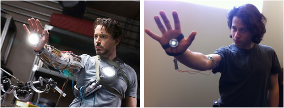
Our project is an analog EMG, or electromyogram, that controls an LED placed in the center of the palm, lighting the device proportionally to the flex in the user’s bicep muscle. This device is meant to simulate Iron Man’s repulsor by emitting an intense light from the palm when the arm is flexed. The final product aims to be clean, simple, and replicable at a low cost.
Procedure
Filters
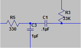
We approached this project by first studying both the EKG lab and Speaker lab from this semester. We knew we would have to measure a voltage difference across a portion of the body as well as filter and amplify the measured signal. These tasks were addressed in the EKG Lab and the Speaker Lab, and reviewing these labs proved to be incredibly helpful in our project. The circuit from the EKG lab provided a reasonable starting point, and with some research we found band pass filter values that are better fitted to our EMG application. A great resource we found was Mechatronics Learning Studio. On this site, students used an Arduino microcontroller to measure the voltage difference across the bicep and used it to open or close a servo driven claw. While their system is binary and requires the use of a microcontroller, their research suggests that a band pass filter that only allows frequencies from 50Hz to 500Hz to pass through would be the ideal filter for our project. According to our research, the 50-500Hz range “is the range of frequencies human nerves can transmit signals”. This filter range is not perfect; it still includes the measurable frequencies produced by nearby electronics and fluorescent lights, but our testing has shown that this noise does not drastically interfere with our measurements.
Envelope Detector
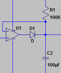
Once we had a better idea of what frequency spectrum we were looking for, our next step was to create a reliable and safe circuit to control the LED. We considered a Schmitt trigger, but decided a proportional brightness control would better fulfill the vision of our project. We contemplated writing a MATLAB script that would take a sample at every small time step, find the difference, and if it was over a threshold, would produce a proportionally higher signal; however, this would require the use of a computer running MATLAB to function. At one point we got a signal that would spike at the beginning of every flex, and then anti-spike at the end thereof. This turned out to be a fluke in our circuit. After working with our circuit some more, we got a signal that would increase in amplitude proportional to how hard the subject would flex their bicep. We were able to measure a signal oscillation about 2.5V with an amplitude spanning 1.5V to 3.5V. When the bicep was flexed, the amplitude of this signal would increase. Next, we added a modified voltage envelope detector that would output a non-oscillating voltage corresponding to the peak voltage of the oscillating signal. A voltage envelope detector consists of a diode which rectifies the oscillating signal, and a resistor and a capacitor in parallel connecting the output of the diode to ground. The rectified signal “fills” the capacitor and the resistor “drains” the capacitor. With the correct capacitor and resistor values, the filling and draining cleanly follows the peaks of the signal. With the use of an op-amp designed to carry enough current to power our large LED and creative use of voltage dividers, we converted the voltage variance from 3.5V to 5.0V to a voltage variance from ~2.0V to 3.0V. It is important the circuit cannot output more than 3.0V in order to protect the LED. With this setup, the LED does not produce any light when the arm is relaxed, and it is supplied with a maximum voltage of 3.0V when the arm is fully flexed. As a final modification, we replaced a resistor with a potentiometer to adjust the sensitivity of the apparatus so that more muscular people were not constantly setting it off and less muscular people could still bring the LED to full brightness.
Circuit Diagram
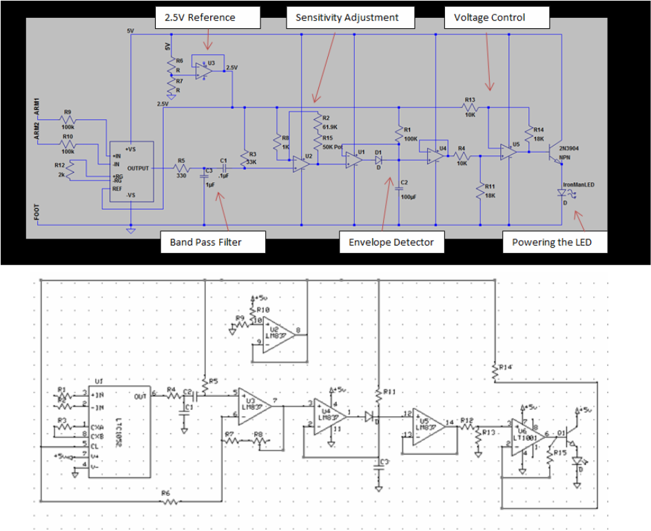
Once we had finished our breadboard prototype, we organized our circuit using two circuit simulation programs: LTSpice and ExpressSCH. We found that it was relatively simple to use both programs, once the basics were learned. While both programs accomplished the same goal, we wanted to gain experience in using multiple tools. Once we had created an organized circuit diagram, we used our schematic to design and construct two compact versions of our circuit on a permanent protoboard. We had hoped that by using ExpressSCH to diagram our schematic we would be able to seamlessly use ExpressPCB to design a printed circuit board which we could then order. However, we were not able to order a PCB due to time constraints. Even though we did not order a PCB to be printed, we did learn what goes into designing a PCB and would be able to do so for any future project.
Data
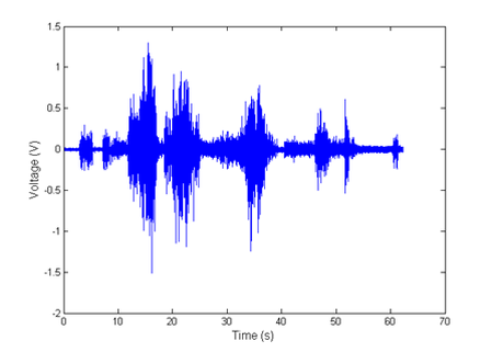
This graph displays the output signal of the generic EKG circuit from Lab 5, with appropriate filter modifications for the muscle. The areas of greater amplitude result when the measured muscle is being flexed. The goal after seeing this signal was to create an envelope detector circuit that would follow the peaks of this signal and therefore increase the voltage enough to power the LED when the muscle is flexed. The envelope detector circuit was implemented effectively and resulted in the following signal, after also implementing an additional amplifier:
|
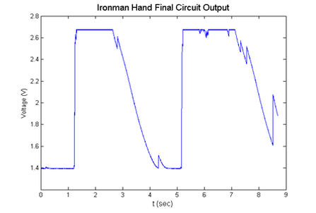
The peaks occur when the muscle is flexed, supplying sufficient voltage to give the LED a bright shine. When it is relaxed, the voltage drops off more slowly than it rose, giving the LED the visual effect of slowly shutting off, like Iron Man’s repulsor beam does.
|
Final Product
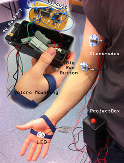 |
To use the Iron Man Hand simply attach one electrode each to your ankle and to either end of your bicep. Attach the equipment box to your belt, and strap the LED setup to your hand. Adjust the potentiometer such that the LED only lights up when you are flexing. Try lifting your arm gently, raising your hand, and flexing your bicep. We strongly encourage the use of sound effects.
 |
Conclusion
While we have made slight adjustments to our goal throughout our process, we were able to accomplish what we originally set out to do. We began with the experience and knowledge we had gained from our labs and we ended with a clean, original, and replicable device.
We completed a working prototype the day we turned in the progress report. Since then we have been streamlining the design, practicing making PCBs, and replicating our success. We now have two fully working products that can be used by anyone. Through this project we learned about the proper voltage and current for LEDs, envelope detectors, choosing correct filters, implementing various kinds of amplifiers using op-amps and instrumentation devices, adjusting for unforeseen error, and turning a disorganized system into a polished final product by making a circuit or device entirely analog. Brad Minch and Brian Storey gave us a lot of help in learning these lessons, taking extra time to explain the finer points of the electronics to us and helping us troubleshoot misbehaving circuits. |
|
Team